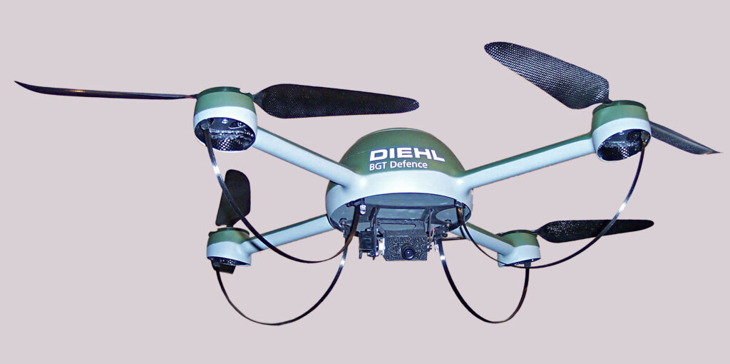
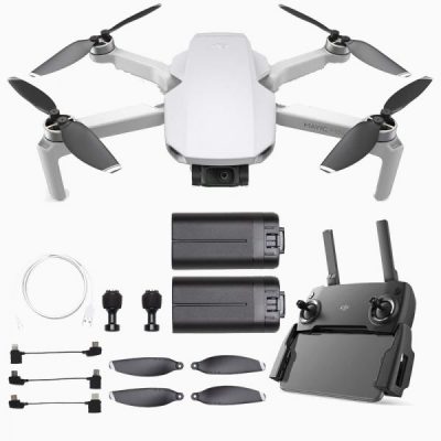
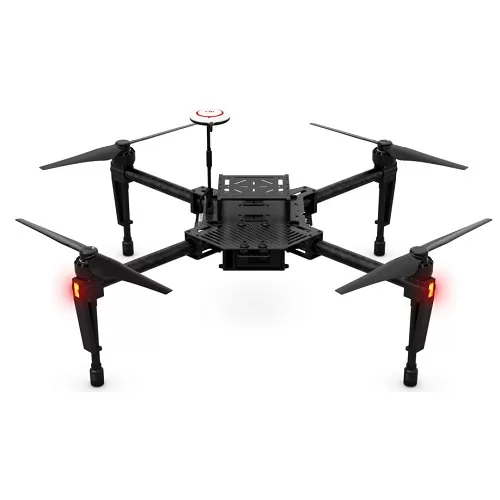
برای هر گیرنده ی رادیو کنترل ، چند فرمت سیگنال خروجی وجود دارد. معمول ترین و رایج ترین نوع سیگنال در رسیور های رادیو کنترل ها، سیگنال PWM است که برای هر کانال یک سیم برای اتصال به فلایت کنترل نیاز دارد. در حال حاضر سیگنال PPM از همه ی سیگنال ها محبوب تر است، چرا که قابلیت اداره کردن 8 کانال را در یک سیگنال دارد. در این مقاله به شما نحوه ی ساخت مبدل برای تبدیل سیگنال PWM به PPM برای رسیور های 2.4GHz با آردوینو را آموزش می دهیم.
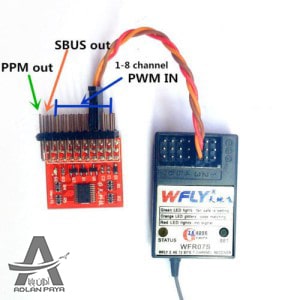
برای آشنایی بیشتر با انواع پروتکل های ارتباطی رسیور های رادیو کنترل های مختلف به این لینک مراجعه کنید.
نحوه ی اتصال رسیور به برد آردوینو
پین های 5V و GND در رسیور را به پین RAW و پین GND در برد آردوینو وصل کنید. همچنین پین های Ch1 تا Ch8 رسیور را به پین های D0 تا D7 برد آردوینو وصل کنید (اگر از رسیوری استفاده می کنید که دارای کانال های کمتری می باشد، پین هایی که روی برد آردوینو خالی می ماند را خالی رها کنید).
برای مثال تصویر زیر را به دقت نگاه کنید.
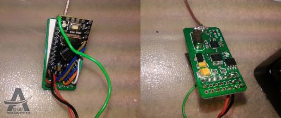
همان طور که در تصویر بالا می بینید، این برد آردوینو مستقیما به یک مبدل سیگنال PWM به PPM تبدیل شده است. 3 سیم به پین های 5V و GND و PPM (سیم سبز رنگ) برد آردوینو متصل شده است. شما می توانید سر دیگر این سه سیم را به فلایت کنترل خود متصل کنید و به همین راحتی یک پروتکل PWM را به یک پروتکل PPM تبدیل کرده اید.
حتی شما می توانید کانال Failsafe را در کانال های خود قرار دهید فقط کافی است که آن را در کد های خود تنظیم کنید.
بارگزاری کد ها روی پلتفرم آردوینو برای تبدیل سیگنال PWM به PPM
کافی است که شما کد های آردوینو ی زیر را ( بدون هیچ گونه تغییری) کپی کرده و در آردوینو ی خود آپلود کنید.
// ------------------------------------------------------------------------------------------------------------------------------------------------------------
//  8 Channel PWM to 1 channel PPM converter for RC receivers, using Arduino
//
//
// ..and has been hacked code to:
//   only support Atmel328 chips ( as found on Arduino Duemilanove or Arduino Uno )  chips
//   not support any "error" mode/s, just 8 PWM-IN  channels TO one single PPM OUT
//   not support any LED indicators m just PWM-IN, and PPM-OUT
//  Integrated the one library that is used to the sketch, for easy user experience.
//   made it Arduino IDE compatible, so it uses standard bootloader and Serial uploader, like all realy Arduino/s.
//  make compile-time option to either "hold last good PPM value" or "hold default value/s" in case of
//   no actual input signal for each channel.   see FAILHOLD and FAILCENTRE in .h file


// .
// ------------------------------------------------------------------------------------------------------------------------------------------------------------
// PREPROCESSOR DIRECTIVES
// ------------------------------------------------------------------------------------------------------------------------------------------------------------

#include "Arduino.h"
#include "ppm_encoder.h"
#include <util/delay.h>
#include <avr/io.h>


#define	ERROR_THRESHOLD		2									// Number of servo input errors before alerting
#define ERROR_DETECTION_WINDOW	3000 * LOOP_TIMER_10MS			// Detection window for error detection (default to 30s)
#define	ERROR_CONDITION_DELAY	500 * LOOP_TIMER_10MS			// Servo error condition LED delay (LED blinking duration)

#define PASSTHROUGH_MODE_ENABLED	// Comment this line to remove CH8 radio passthrough mode support (hardware failsafe for Arduplane)
#define PASSTHROUGH_CHANNEL		8 * 2	// Channel for passthrough mode selection
#define PASSTHROUGH_CHANNEL_OFF_US		ONE_US * 1600 - PPM_PRE_PULSE	// Passthrough off threshold
#define PASSTHROUGH_CHANNEL_ON_US		ONE_US * 1800 - PPM_PRE_PULSE	// Passthrough on threshold

#define THROTTLE_CHANNEL		3 * 2	// Throttle Channel
#define THROTTLE_CHANNEL_LED_TOGGLE_US		ONE_US * 1200 - PPM_PRE_PULSE	// Throttle Channel Led toggle threshold
#define LED_LOW_BLINKING_RATE	125 * LOOP_TIMER_10MS // Led blink rate for low throttle position (half period)

// Timers

#define TIMER0_10MS		156			// Timer0 ticks for 10 ms duration
#define TIMER1_10MS		20000		// Timer1 ticks for 10 ms duration
#define TIMER2_100MS		1562	// Timer2 ticks for 100 ms duration
#define LOOP_TIMER_10MS	10			// Loop timer ticks for 10 ms duration

// LED Code

#define	SPACE_SHORT_DURATION	40 * LOOP_TIMER_10MS	// Space after short symbol
#define	SPACE_LONG_DURATION	75 * LOOP_TIMER_10MS		// Space after long symbol
#define	SYMBOL_SHORT_DURATION	20 * LOOP_TIMER_10MS	// Short symbol duration
#define	SYMBOL_LONG_DURATION	100 * LOOP_TIMER_10MS	// Long symbol duration
#define	INTER_CODE_DURATION	150 * LOOP_TIMER_10MS		// Inter code duration

#define INTER_CODE		0		// Symbols value for coding
#define SHORT_SYMBOL	1
#define LONG_SYMBOL		2
#define SHORT_SPACE		3
#define LONG_SPACE		4
#define LOOP			5


// ------------------------------------------------------------------------------------------------------------------------------------------------------------
// PPM ENCODER INIT AND AUXILIARY TASKS
// ------------------------------------------------------------------------------------------------------------------------------------------------------------

	// ------------------------------------------------------------------------------------------------------------------------------------------------------------
	// LOCAL VARIABLES
	// ------------------------------------------------------------------------------------------------------------------------------------------------------------
	bool localinit = true; // We are inside init sequence
	bool mux_passthrough = false; // Mux passthrough mode status Flag : passthrough is off
	uint16_t led_acceleration; // Led acceleration based on throttle stick position
	bool servo_error_condition = false;	//	Servo signal error condition

	static uint16_t servo_error_detection_timer=0;		// Servo error detection timer
	static uint16_t servo_error_condition_timer=0; 		// Servo error condition timer
	static uint16_t blink_led_timer = 0; 		// Blink led timer

	#ifdef PASSTHROUGH_MODE_ENABLED
	static uint8_t mux_timer = 0;				// Mux timer
	static uint8_t mux_counter = 0;				// Mux counter
	static int8_t mux_check = 0;
	static uint16_t mux_ppm = 500;
	#endif

	static uint16_t led_code_timer = 0;	// Blink Code Timer
	static uint8_t led_code_symbol = 0;	// Blink Code current symbol


	// ------------------------------------------------------------------------------------------------------------------------------------------------------------
	// LOCAL FUNCTIONS
	// ------------------------------------------------------------------------------------------------------------------------------------------------------------

	// ------------------------------------------------------------------------------
	// Led blinking (non blocking) function
	// ------------------------------------------------------------------------------

	uint8_t blink_led ( uint16_t half_period )	// ( half_period max = 65 s )
	{

		blink_led_timer++;

		if ( blink_led_timer < half_period ) // If half period has not been reached
		{
			return 0; // Exit timer function and return 0
		}
		else	// half period reached - LED Toggle
		{
			PPM_PORT ^= ( 1 << PB0 );	// Toggle status LED
			blink_led_timer = 0;	// Blink led timer reset

			return 1;	// half period reached - Exit timer function and return 1
		}

	}

	// ------------------------------------------------------------------------------
	// Led code (non blocking) function
	// ------------------------------------------------------------------------------

	void blink_code_led ( uint8_t code )
	{

		const uint8_t coding[2][14] = {

		// PPM_PASSTROUGH_MODE
		{ INTER_CODE, LONG_SYMBOL, LONG_SPACE, SHORT_SYMBOL, SHORT_SPACE, SHORT_SYMBOL, LOOP },

		// JETI_MODE
		{ INTER_CODE, LONG_SYMBOL, LONG_SPACE, SHORT_SYMBOL, SHORT_SPACE, SHORT_SYMBOL, SHORT_SPACE, SHORT_SYMBOL,LOOP }

		};

		led_code_timer++;


			switch ( coding [ code - 2 ] [ led_code_symbol ] )
			{
				case INTER_CODE:

				if ( led_code_timer < ( INTER_CODE_DURATION ) ) return;
				else PPM_PORT |= ( 1 << PB0 );		// Enable status LED
				break;

				case LONG_SYMBOL:	// Long symbol

				if ( led_code_timer < ( SYMBOL_LONG_DURATION ) ) return;
				else PPM_PORT &= ~( 1 << PB0 );	// Disable status LED
				break;

				case SHORT_SYMBOL:	// Short symbol

				if ( led_code_timer < ( SYMBOL_SHORT_DURATION ) ) return;
				else PPM_PORT &= ~( 1 << PB0 );	// Disable status LED
				break;

				case SHORT_SPACE:	// Short space

				if ( led_code_timer < ( SPACE_SHORT_DURATION ) ) return;
				else PPM_PORT |= ( 1 << PB0 );		// Enable status LED
				break;

				case LONG_SPACE:	// Long space

				if ( led_code_timer < ( SPACE_LONG_DURATION ) ) return;
				else PPM_PORT |= ( 1 << PB0 );		// Enable status LED
				break;

				case LOOP:	// Loop to code start
				led_code_symbol = 0;
				return;
				break;

			}

		led_code_timer = 0;	// Code led timer reset
		led_code_symbol++;	// Next symbol

		return; // LED code function return

	}


	// ------------------------------------------------------------------------------
	// ppm reading helper - interrupt safe and non blocking function
	// ------------------------------------------------------------------------------
	uint16_t ppm_read( uint8_t channel )
	{
		uint16_t ppm_tmp = ppm[ channel ];
		while( ppm_tmp != ppm[ channel ] ) ppm_tmp = ppm[ channel ];

		return ppm_tmp;
	}

	// ------------------------------------------------------------------------------------------------------------------------------------------------------------
	// INITIALISATION CODE
	// ------------------------------------------------------------------------------------------------------------------------------------------------------------

void setup() {


	// ------------------------------------------------------------------------------
	// Reset Source checkings
	// ------------------------------------------------------------------------------
	if (MCUSR & 1)	// Power-on Reset
	{
	   MCUSR=0; // Clear MCU Status register
	   // custom code here
	}
	else if (MCUSR & 2)	// External Reset
	{
	   MCUSR=0; // Clear MCU Status register
	   // custom code here
	}
	else if (MCUSR & 4)	// Brown-Out Reset
	{
	   MCUSR=0; // Clear MCU Status register
	   brownout_reset=true;
	}
	else	// Watchdog Reset
	{
	   MCUSR=0; // Clear MCU Status register
	   // custom code here
	}


	// ------------------------------------------------------------------------------
	// Servo input and PPM generator init
	// ------------------------------------------------------------------------------
	ppm_encoder_init();

	// ------------------------------------------------------------------------------
	// Outputs init
	// ------------------------------------------------------------------------------
	PPM_DDR |= ( 1 << PB0 );	// Set LED pin (PB0) to output
	PPM_DDR |= ( 1 << PB1 );	// Set MUX pin (PB1) to output
	PPM_DDR |= ( 1 << PPM_OUTPUT_PIN );	// Set PPM pin (PPM_OUTPUT_PIN, OC1B) to output

	// ------------------------------------------------------------------------------
	// Timer0 init (normal mode) used for LED control and custom code
	// ------------------------------------------------------------------------------
	TCCR0A = 0x00;	// Clock source: System Clock
	TCCR0B = 0x05;	// Set 1024x prescaler - Clock value: 15.625 kHz - 16 ms max time
	TCNT0 = 0x00;
	OCR0A = 0x00;		// OC0x outputs: Disconnected
	OCR0B = 0x00;
	TIMSK0 = 0x00;		// Timer 1 interrupt disable

	// ------------------------------------------------------------------------------
	// Enable global interrupt
	// ------------------------------------------------------------------------------
	sei();			// Enable Global interrupt flag

	// ------------------------------------------------------------------------------
	// Disable radio passthrough (mux chip A/B control)
	// ------------------------------------------------------------------------------
	PPM_PORT |= ( 1 << PB1 );	// Set PIN B1 to disable Radio passthrough (mux)


}

void loop() {


	// ------------------------------------------------------------------------------------------------------------------------------------------------------------
	// AUXILIARY TASKS
	// ------------------------------------------------------------------------------------------------------------------------------------------------------------
	PWM_LOOP: // SERVO_PWM_MODE
	while( 1 )
	{

		_delay_us (950); // Slow down while loop

	}	// PWM Loop end


} // main lopo function end
سپس یک صفحه ی جدید در Arduino IDE خود ایجاد کنید نام آن ppm_encoder.h قرار دهید و کد زیر را در در آن قرار دهید.
// -------------------------------------------------------------

#ifndef _PPM_ENCODER_H_
#define _PPM_ENCODER_H_

#include <avr/io.h>

// -------------------------------------------------------------

#include <avr/interrupt.h>
#include <avr/wdt.h>
#include <util/delay.h>

// -------------------------------------------------------------
// SERVO INPUT FILTERS
// -------------------------------------------------------------
// Using both filters is not recommended and may reduce servo input resolution

// #define _AVERAGE_FILTER_         // Average filter to smooth servo input capture jitter
// #define _JITTER_FILTER_             // Cut filter to remove 0,5us servo input capture jitter
// -------------------------------------------------------------

#ifndef F_CPU
#define F_CPU               16000000UL
#endif

#ifndef true
#define true                1
#endif

#ifndef false
#define false               0
#endif

//#ifndef bool
//#define bool                boolean
//#endif
// 328 does not define PBX but defines an equivalent as PORTBX, comment these lines out if you already have a PB2 defined.
#define PB2 PORTB2
#define PB1 PORTB1
#define PB0 PORTB0


// -------------------------------------------------------------
// SERVO INPUT MODE - !EXPERIMENTAL!
// -------------------------------------------------------------

#define SERVO_PWM_MODE        1    // Normal 8 channel servo (pwm) input

// Servo input mode (jumper (default), pwm, ppm, jeti or spektrum)
volatile uint8_t servo_input_mode = SERVO_PWM_MODE;
// -------------------------------------------------------------

// Number of Timer1 ticks in one microsecond
#define ONE_US                F_CPU / 8 / 1000 / 1000

// 400us PPM pre pulse
#define PPM_PRE_PULSE         ONE_US * 400

// -------------------------------------------------------------
// SERVO LIMIT VALUES
// -------------------------------------------------------------

// Servo minimum position
#define PPM_SERVO_MIN         ONE_US * 900 - PPM_PRE_PULSE

// Servo center position
#define PPM_SERVO_CENTER      ONE_US * 1500 - PPM_PRE_PULSE

// Servo maximum position
#define PPM_SERVO_MAX         ONE_US * 2100 - PPM_PRE_PULSE

// Throttle default at power on
#define PPM_THROTTLE_DEFAULT  ONE_US * 1100 - PPM_PRE_PULSE

// Throttle during failsafe
#define PPM_THROTTLE_FAILSAFE ONE_US * 900 - PPM_PRE_PULSE

// CH5 power on values (mode selection channel)
//#define PPM_CH5_MODE_4        ONE_US * 1555 - PPM_PRE_PULSE

// -------------------------------------------------------------

// Number of servo input channels
#define SERVO_CHANNELS        8

// PPM period 18.5ms - 26.5ms (54hz - 37Hz)
#define PPM_PERIOD            ONE_US * ( 22500 - ( 8 * 1500 ) )

// Size of ppm[..] data array ( servo channels * 2 + 2)
#define PPM_ARRAY_MAX         18


// Data array for storing ppm (8 channels) pulse widths.
volatile uint16_t ppm[ PPM_ARRAY_MAX ] =
{
    PPM_PRE_PULSE,
    PPM_SERVO_CENTER,         // Channel 1
    PPM_PRE_PULSE,
    PPM_SERVO_CENTER,         // Channel 2
    PPM_PRE_PULSE,
    PPM_THROTTLE_DEFAULT,     // Channel 3 (throttle)
    PPM_PRE_PULSE,
    PPM_SERVO_CENTER,         // Channel 4
    PPM_PRE_PULSE,
    PPM_SERVO_CENTER,           // Channel 5
    PPM_PRE_PULSE,
    PPM_SERVO_CENTER,         // Channel 6
    PPM_PRE_PULSE,
    PPM_SERVO_CENTER,         // Channel 7
    PPM_PRE_PULSE,
    PPM_SERVO_CENTER,         // Channel 8
    PPM_PRE_PULSE,
    PPM_PERIOD
};


// -------------------------------------------------------------
// SERVO FAILSAFE VALUES
// -------------------------------------------------------------
const uint16_t failsafe_ppm[ PPM_ARRAY_MAX ] =
{
    PPM_PRE_PULSE,
    PPM_SERVO_CENTER,         // Channel 1
    PPM_PRE_PULSE,
    PPM_SERVO_CENTER,         // Channel 2
    PPM_PRE_PULSE,
    PPM_THROTTLE_FAILSAFE,    // Channel 3 (throttle)
    PPM_PRE_PULSE,
    PPM_SERVO_CENTER,         // Channel 4
    PPM_PRE_PULSE,
    PPM_SERVO_CENTER,           // Channel 5
    PPM_PRE_PULSE,
    PPM_SERVO_CENTER,         // Channel 6
    PPM_PRE_PULSE,
    PPM_SERVO_CENTER,         // Channel 7
    PPM_PRE_PULSE,
    PPM_SERVO_CENTER,         // Channel 8
    PPM_PRE_PULSE,
    PPM_PERIOD
};
// -------------------------------------------------------------


// AVR parameters for ArduPilot MEGA v1.4 PPM Encoder (ATmega328P)
#if defined (__AVR_ATmega328P__) || defined (__AVR_ATmega328__)


#define SERVO_DDR             DDRD
#define SERVO_PORT            PORTD
#define SERVO_INPUT           PIND
// PCIE2 PC Interrupt enable 2 is for Arduino Pins (D0-D7), also called PORTD.
#define SERVO_INT_VECTOR      PCINT2_vect

#define SERVO_INT_MASK        PCMSK2
#define SERVO_INT_CLEAR_FLAG  PCIF2
#define SERVO_INT_ENABLE      PCIE2
#define SERVO_TIMER_CNT       TCNT1

#define PPM_DDR               DDRB
#define PPM_PORT              PORTB
#define PPM_OUTPUT_PIN        PB2
#define PPM_INT_VECTOR        TIMER1_COMPB_vect
#define PPM_COMPARE           OCR1B
#define PPM_COMPARE_FLAG      COM1B0
#define PPM_COMPARE_ENABLE    OCIE1B

#else
#error NO SUPPORTED DEVICE FOUND! ( ATmega328/p)
#endif

// Used to indicate invalid SERVO input signals
//volatile uint8_t servo_input_errors = 0;

// Used to indicate missing SERVO input signals
volatile bool servo_input_missing = true;

// Used to indicate if PPM generator is active
volatile bool ppm_generator_active = false;

// Used to indicate a brownout restart
volatile bool brownout_reset = false;

// ------------------------------------------------------------------------------
// PPM GENERATOR START - TOGGLE ON COMPARE INTERRUPT ENABLE
// ------------------------------------------------------------------------------
// this starts OUTGOING PPM stream on PPM_PORT (PORTB, Arduino D8-D13)  at PPM_OUTPUT_PIN (PB2, arduino pin D10)
void ppm_start( void )
{
        // Prevent reenabling an already active PPM generator
        if( ppm_generator_active ) return;

        // Store interrupt status and register flags
        uint8_t SREG_tmp = SREG;

        // Stop interrupts
        cli();


        // Make sure initial output state is low
        PPM_PORT &= ~(1 << PPM_OUTPUT_PIN);

        // Wait for output pin to settle
        //_delay_us( 1 );

        // Set initial compare toggle to maximum (32ms) to give other parts of the system time to start
        SERVO_TIMER_CNT = 0;
        PPM_COMPARE = 0xFFFF;

        // Set toggle on compare output
        TCCR1A = (1 << PPM_COMPARE_FLAG);

        // Set TIMER1 8x prescaler
        TCCR1B = ( 1 << CS11 );

        // Enable output compare interrupt
        TIMSK1 |= (1 << PPM_COMPARE_ENABLE);

        // Indicate that PPM generator is active
        ppm_generator_active = true;

        // Restore interrupt status and register flags
        SREG = SREG_tmp;

}

// ------------------------------------------------------------------------------
// PPM GENERATOR STOP - TOGGLE ON COMPARE INTERRUPT DISABLE
// ------------------------------------------------------------------------------
void ppm_stop( void )
{
        // Store interrupt status and register flags
        uint8_t SREG_tmp = SREG;

        // Stop interrupts
        cli();

        // Disable output compare interrupt
        TIMSK1 &= ~(1 << PPM_COMPARE_ENABLE);

        // Reset TIMER1 registers
        TCCR1A = 0;
        TCCR1B = 0;

        // Indicate that PPM generator is not active
        ppm_generator_active = false;

        // Restore interrupt status and register flags
        SREG = SREG_tmp;

}

// ------------------------------------------------------------------------------
// Watchdog Interrupt (interrupt only mode, no reset)
// ------------------------------------------------------------------------------
ISR( WDT_vect ) // If watchdog is triggered then enable missing signal flag and copy power on or failsafe positions
{
    // Use failsafe values if PPM generator is active or if chip has been reset from a brown-out
    if ( ppm_generator_active || brownout_reset )
    {
        // Copy failsafe values to ppm[..]
        for ( uint8_t i = 0; i < PPM_ARRAY_MAX; i++ ) { ppm[ i ] = failsafe_ppm[ i ]; } } // Set missing receiver signal flag servo_input_missing = true; // Reset servo input error flag //servo_input_errors = 0; } // ------------------------------------------------------------------------------ // ------------------------------------------------------------------------------ // SERVO/PPM INPUT - PIN CHANGE INTERRUPT, for any Arduino pin D0 -> D7
// ------------------------------------------------------------------------------
ISR( SERVO_INT_VECTOR )
{


    // Servo pulse start timing
    static uint16_t servo_start[ SERVO_CHANNELS ] = { 0, 0, 0, 0, 0, 0, 0, 0 };


	// Missing throttle signal failsafe
	static uint8_t throttle_timeout = 0;

	// Servo input pin storage
    static uint8_t servo_pins_old = 0;

    // Used to store current servo input pins
    uint8_t servo_pins;

    // Read current servo pulse change time
    uint16_t servo_time = SERVO_TIMER_CNT;


    // ------------------------------------------------------------------------------
    // SERVO PWM MODE
    // ------------------------------------------------------------------------------
CHECK_PINS_START: // Start of servo input check

    // Store current servo input pins
    servo_pins = SERVO_INPUT;

    // Calculate servo input pin change mask
    uint8_t servo_change = servo_pins ^ servo_pins_old;

    // Set initial servo pin and channel
    uint8_t servo_pin = 1;
    uint8_t servo_channel = 0;

CHECK_PINS_LOOP: // Input servo pin check loop

    // Check for pin change on current servo channel
    if( servo_change & servo_pin )
    {
     // if (( servo_pin == 1  )  && (  ppm_generator_active = false) ) ppm_start();
     // if (( servo_pin == 8  )  && (  ppm_generator_active = true) ) ppm_stop();
        // High (raising edge)
        if( servo_pins & servo_pin )
        {
            servo_start[ servo_channel ] = servo_time;
        }
        else
        {

            // Get servo pulse width
            uint16_t servo_width = servo_time - servo_start[ servo_channel ] - PPM_PRE_PULSE;

            // Calculate servo channel position in ppm[..]
            uint8_t _ppm_channel = ( servo_channel << 1 ) + 1; // Check that servo pulse signal is valid before sending to ppm encoder if( servo_width > PPM_SERVO_MAX ) goto CHECK_PINS_ERROR;
            if( servo_width < PPM_SERVO_MIN ) goto CHECK_PINS_ERROR; goto CHECK_PINS_NOERROR; CHECK_PINS_ERROR: // on width input error, use defailt/failsave value, OR previous value // choose the error handling type here! #define FAILCENTRE 1 #ifdef FAILCENTRE servo_width = failsafe_ppm[ _ppm_channel ]; // failsafe defaults, most channels centred, throttle lowered. #endif #ifdef FAILHOLD servo_width = ppm[ _ppm_channel ]; // all channels hold their previous position! #endif CHECK_PINS_NOERROR: //Reset throttle failsafe timeout if( _ppm_channel == 5 ) throttle_timeout = 0; #ifdef _AVERAGE_FILTER_ // Average filter to smooth input jitter servo_width += ppm[ _ppm_channel ]; servo_width >>= 1;
        #endif

        #ifdef _JITTER_FILTER_
            // 0.5us cut filter to remove input jitter
            int16_t ppm_tmp = ppm[ _ppm_channel ] - servo_width;
            if( ppm_tmp == 1 ) goto CHECK_PINS_NEXT;
            if( ppm_tmp == -1 ) goto CHECK_PINS_NEXT;
        #endif

            // Update ppm[..]
            ppm[ _ppm_channel ] = servo_width;
        }
    }

CHECK_PINS_NEXT:

    // Select next servo pin
    servo_pin <<= 1;

    // Select next servo channel
    servo_channel++;

    // Check channel and process if needed
    if( servo_channel < SERVO_CHANNELS ) goto CHECK_PINS_LOOP; goto CHECK_PINS_DONE; // All servo input pins has now been processed CHECK_PINS_DONE: // Reset Watchdog Timer wdt_reset(); // Set servo input missing flag false to indicate that we have received servo input signals servo_input_missing = false; // Store current servo input pins for next check servo_pins_old = servo_pins; // Start PPM generator if not already running if( ppm_generator_active == false ) ppm_start(); // Throttle failsafe if( throttle_timeout++ >= 128 )
	{
		// Reset throttle timeout
		throttle_timeout = 0;
		// Set throttle failsafe value
		ppm[ 5 ] = PPM_THROTTLE_FAILSAFE;
	}

    //Has servo input changed while processing pins, if so we need to re-check pins
    if( servo_pins != SERVO_INPUT ) goto CHECK_PINS_START;

    // Clear interrupt event from already processed pin changes
    PCIFR |= (1 << SERVO_INT_CLEAR_FLAG); } // ------------------------------------------------------------------------------ // ------------------------------------------------------------------------------ // PPM OUTPUT - TIMER1 COMPARE INTERRUPT // ------------------------------------------------------------------------------ ISR( PPM_INT_VECTOR ) { // Current active ppm channel static uint8_t ppm_channel = PPM_ARRAY_MAX - 1; // Update timing for next compare toggle PPM_COMPARE += ppm[ ppm_channel ]; // Select the next ppm channel if( ++ppm_channel >= PPM_ARRAY_MAX )
	{
		ppm_channel = 0;
	}
}
// ------------------------------------------------------------------------------

// ------------------------------------------------------------------------------
// PPM READ - INTERRUPT SAFE PPM SERVO CHANNEL READ
// ------------------------------------------------------------------------------
/* uint16_t ppm_read_channel( uint8_t channel )
{
    // Limit channel to valid value
    uint8_t _channel = channel;
    if( _channel == 0 ) _channel = 1;
    if( _channel > SERVO_CHANNELS ) _channel = SERVO_CHANNELS;

    // Calculate ppm[..] position
    uint8_t ppm_index = ( _channel << 1 ) + 1;

    // Read ppm[..] in a non blocking interrupt safe manner
    uint16_t ppm_tmp = ppm[ ppm_index ];
    while( ppm_tmp != ppm[ ppm_index ] ) ppm_tmp = ppm[ ppm_index ];

    // Return as normal servo value
    return ppm_tmp + PPM_PRE_PULSE;
}
*/
// ------------------------------------------------------------------------------

// ------------------------------------------------------------------------------
// PPM ENCODER INIT
// ------------------------------------------------------------------------------
void ppm_encoder_init( void )
{


    // SERVO/PPM INPUT PINS
    // ------------------------------------------------------------------------------
    // Set all servo input pins to inputs
    SERVO_DDR = 0;

    // Activate pullups on all input pins
    SERVO_PORT |= 0xFF;


    // SERVO/PPM INPUT - PIN CHANGE INTERRUPT
    // ------------------------------------------------------------------------------
    if( servo_input_mode == SERVO_PWM_MODE )
    {
        // Set servo input interrupt pin mask to all 8 servo input channels
        SERVO_INT_MASK = 0xFF;
    }

    // Enable servo input interrupt
    PCICR |= (1 << SERVO_INT_ENABLE);

    // PPM OUTPUT PIN
    // ------------------------------------------------------------------------------
    // Set PPM pin to output
    PPM_DDR |= (1 << PPM_OUTPUT_PIN);

    // ------------------------------------------------------------------------------
    // Enable watchdog interrupt mode
    // ------------------------------------------------------------------------------
    // Disable watchdog
    wdt_disable();
     // Reset watchdog timer
    wdt_reset();
// Start timed watchdog setup sequence
WDTCSR |= (1<<WDCE) | (1<<WDE );
// Set 250 ms watchdog timeout and enable interrupt
WDTCSR = (1<<WDIE) | (1<<WDP2);
}
// ——————————————————————————
به همین راحتی!!


